
The Functions and Classification of Transformer Bobbins
Transformer Bobbin - Functions
- Provides winding space for the copper wires in the transformer.
- Secures the magnetic core inside the transformer.
- The wire slots in the bobbin offer a path for wire routing during the transformer's winding process.
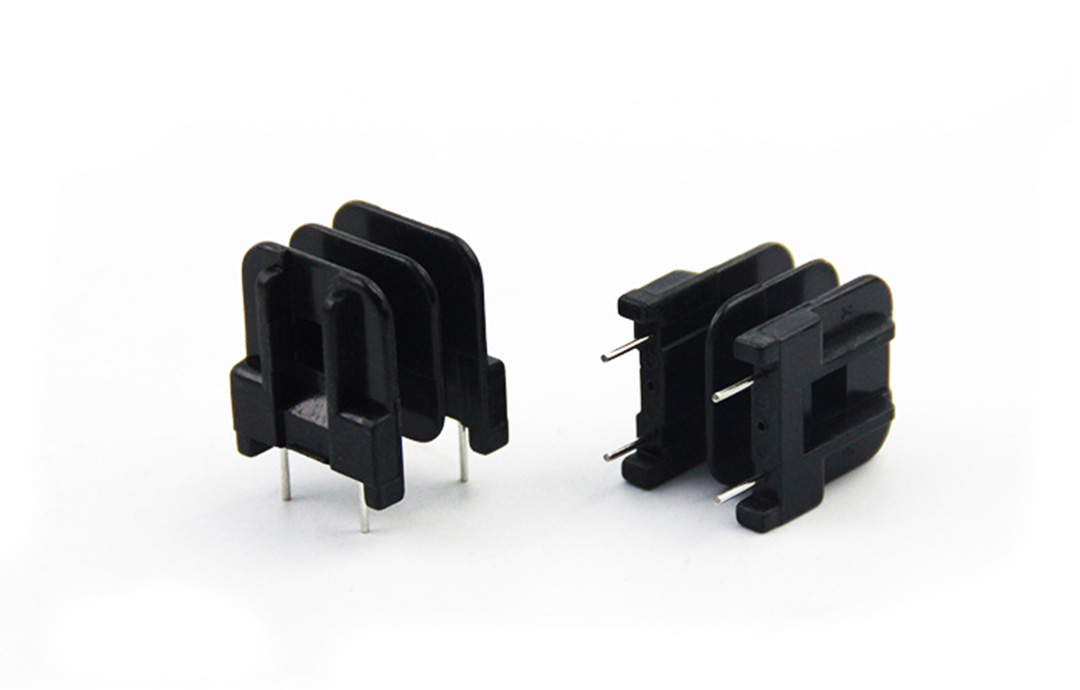
- The metal pins in the bobbin serve as supports for winding the transformer's copper wires; after soldering, they connect to the PCB board and conduct electricity when the transformer operates.
- The retaining wall at the bottom of the bobbin fixes the transformer to the PCB board; it maintains a certain distance between the solder piles (formed during soldering) and the PCB board, as well as between the magnetic core and the PCB board, and isolates the magnetic core from the solder piles to prevent poor voltage resistance.
- The bumps, dimples or chamfers in the bobbin determine the placement direction or pin sequence of the transformer during use.
Transformer Bobbin - Classification
Bobbins are generally classified by the type of magnetic core (or iron core) used in the transformer, including models such as EI, EE, EF, EPC, ER, RM, PQ, and UU. Each model can be further distinguished by the size of the magnetic core (or iron core), e.g., models of different sizes like EE5, EE8, EE13, and EE19.
Bobbins are categorized as follows:
-
By shape: Vertical and horizontal types;
-
By the operating frequency of the transformer: High-frequency bobbins and low-frequency bobbins. The "frequency" here refers to the number of periodic changes of the transformer during operation (measured in Hertz (Hz), also commonly in kilohertz (kHz), megahertz (MHz) or gigahertz (GHz)), not the number of uses;
-
By the application nature of the bobbin pins: Traditional bobbins (DIP) and surface-mount bobbins (SMD).